Project_1_ESP32_Inputs_Outputs.ino, then open it in the Arduino IDE (setup: Foundation 3).
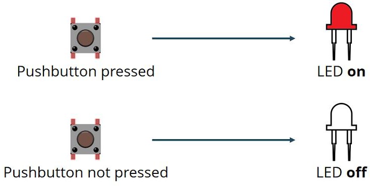
diagram.json above and paste its wiring in to load the circuit.
🎯 Objective
By the end of this project, you will:
- Understand what a GPIO pin is and how the same pin can be an input or an output.
- Configure pins with
pinMode()and know why that belongs insetup(). - Read a pushbutton with
digitalRead()and drive an LED withdigitalWrite(). - Explain why a floating input is a problem, and fix it with a pull-down resistor.
- Recognise contact bounce and handle it with a short debounce delay.
- Wire an LED safely, respecting polarity and using a current-limiting resistor.
1What the sketch does
pinMode(buttonPin, INPUT);   // GPIO 4: read the button
pinMode(ledPin,   OUTPUT);  // GPIO 5: drive the LED

buttonState = digitalRead(buttonPin);
if (buttonState == HIGH) digitalWrite(ledPin, HIGH); // pressed  -> LED on
else                     digitalWrite(ledPin, LOW);  // released -> LED off
The LED lights when the pin reads HIGH, so the button sends 3.3 V to GPIO 4 when pressed, and a 10 kΩ pull‑down holds the pin LOW when released.
INPUT has no internal pull resistor, so the external 10 kΩ pull‑down is required: otherwise the pin "floats" and reads random noise. (§7 shows a software‑only alternative.)2The pins: analog or digital?
| Signal | GPIO | Used as | Here it is | Analog capable? |
|---|---|---|---|---|
| Button | GPIO 4 | digitalRead() | DIGITAL input | Yes: ADC2_CH0 + touch T0 (unused) |
| LED | GPIO 5 | digitalWrite() | DIGITAL output | No: no ADC (PWM only) |
Both pins are used digitally (HIGH/LOW). Use 3V3 (never 5V) for the button's HIGH side.
3Parts Required
| Qty | Part | Notes |
|---|---|---|
| 1 | ESP32 DEVKIT V1 · breadboard · jumper wires | - |
| 1 | LED | Any color: has polarity (§5) |
| 1 | 220 Ω resistor | LED limit · Red‑Red‑Black‑Black‑Brown |
| 1 | 10 kΩ resistor | Pull‑down · Brown‑Black‑Black‑Red‑Brown |
| 1 | Pushbutton | 4‑leg tactile |
4Wiring the Circuit
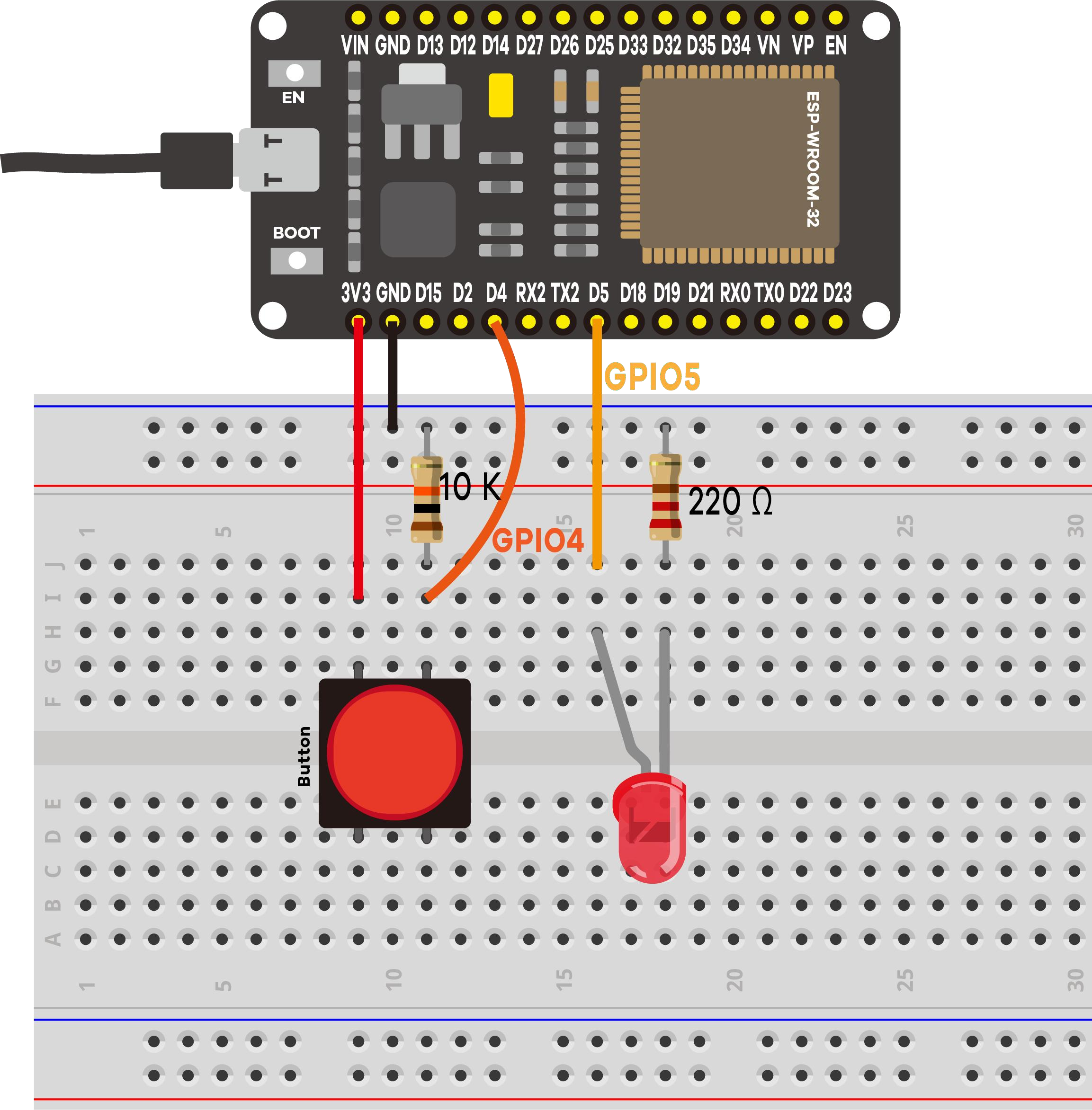
LED circuit (output, GPIO 5)
- GPIO 5 → 220 Ω → LED anode (long leg, +)
- LED cathode (short leg, −) → GND rail
Button circuit (input, GPIO 4)
- One side of the button → 3.3 V rail
- Other side → GPIO 4
- From that same GPIO 4 node → 10 kΩ → GND rail
5LED polarity (don't skip)
LONG leg  = Anode  (+)  -> toward the 220 Ω / GPIO 5 side
SHORT leg = Cathode (-)  -> toward GND   (flat notch on the rim = - side)
If the LED never lights, check first that it isn't reversed.
6Code Walkthrough: Understanding the Sketch
Let's walk through the sketch so you understand what each line does and why.
Step 1: Pin definitions & state variables
const int buttonPin = 4;  // the pushbutton pin (digital input)
const int ledPin    = 5;  // the LED pin        (digital output)

int buttonState = 0;       // this round's reading: HIGH or LOW
int lastButtonState = -1;  // the previous reading, so we can spot changes
Naming the pins with const int means the number appears once: rewire the LED to another GPIO and you change one line. lastButtonState starts at -1, a value digitalRead() can never return, so the first real reading always counts as a change.
Step 2: one-time preparation in setup()
void setup() {
  Serial.begin(115200);        // open the USB link to the computer
  delay(500);                  // let the Serial Monitor connect

  pinMode(buttonPin, INPUT);   // GPIO 4 becomes an input
  pinMode(ledPin, OUTPUT);     // GPIO 5 becomes an output
}
setup() runs once at power-up or reset. pinMode() decides the direction of a pin: an input listens for a voltage someone else supplies, an output drives the pin to 3.3 V or 0 V itself. Every GPIO can do either, so you must say which you want.
Step 3: loop() reads → compares → acts
void loop() {
  buttonState = digitalRead(buttonPin);      // 1. READ the button

  if (buttonState != lastButtonState) {      // 2. did it CHANGE?
    if (buttonState == HIGH) {
      digitalWrite(ledPin, HIGH);            // 3. pressed  -> LED on
      Serial.println("[EVENT] Button PRESSED  -> LED is ON");
    } else {
      digitalWrite(ledPin, LOW);             //    released -> LED off
      Serial.println("[EVENT] Button RELEASED -> LED is OFF");
    }
    lastButtonState = buttonState;           // 4. remember for next time
  }

  delay(50);                                 // 5. debounce
}
loop() runs again and again forever, thousands of times per second. The if comparing this reading with the last one is what keeps the Serial Monitor usable: without it, holding the button down would print the same line endlessly.
Key concepts: what each line really does
| Code | What it does |
|---|---|
pinMode(pin, INPUT) | Sets the pin to listen. Plain INPUT connects no internal resistor, so an unconnected pin floats and reads random noise. That is why the 10 kΩ pull-down is required here. |
pinMode(pin, OUTPUT) | Lets the pin drive itself to 3.3 V (HIGH) or 0 V (LOW), supplying current to whatever is attached. |
digitalRead(pin) | Samples the pin right now and returns HIGH or LOW. Above roughly 2.0 V reads HIGH, below about 0.8 V reads LOW. |
digitalWrite(pin, HIGH) | Connects the pin to 3.3 V, so current flows through the 220 Ω resistor and the LED lights. LOW connects it to 0 V and the LED goes dark. |
buttonState != lastButtonState | Edge detection: acts only when the state differs from last time, turning a continuous stream of readings into discrete press and release events. |
delay(50) | Waits 50 ms. A mechanical button does not switch cleanly: its contacts bounce for a few milliseconds, which one press can register as several. Waiting past the bounce fixes it. |
Expected output on the Serial Monitor
========================================
 Project 1: ESP32 Inputs & Outputs
========================================
Button (input)  -> GPIO 4
LED    (output) -> GPIO 5
Press the button to turn the LED ON.
Waiting for button presses...
----------------------------------------
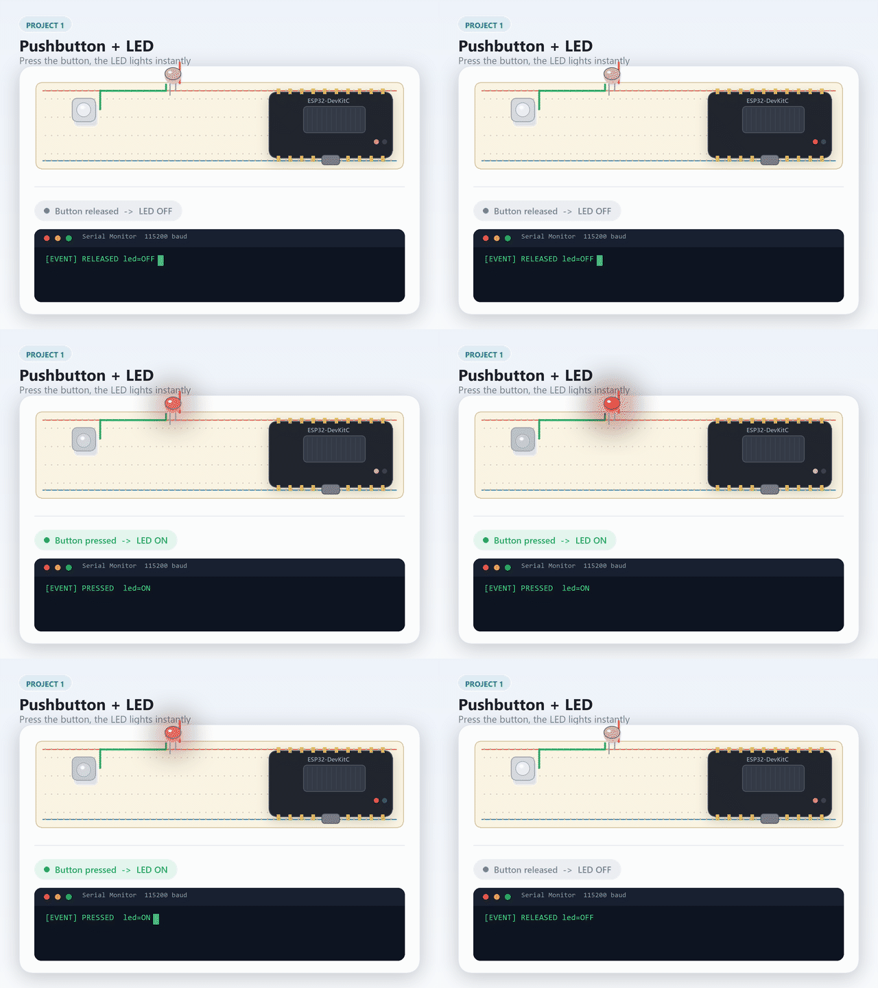
[EVENT] Button PRESSED  -> LED is ON
[EVENT] Button RELEASED -> LED is OFF
Each press and release prints exactly one line. If a single press prints several, the debounce delay is too short for your button.
7Optional: no external resistor (software pull‑up)
Wire the button between GPIO 4 and GND and enable the internal pull‑up. This inverts the logic:
pinMode(buttonPin, INPUT_PULLUP);   // reads HIGH when NOT pressed
if (buttonState == LOW) digitalWrite(ledPin, HIGH); // pressed  -> LED on
else                    digitalWrite(ledPin, LOW);  // released -> LED off
INPUT_PULLUP + flipped code. Don't mix them.INPUT_PULLUP makes the button active-low: a LOW signal means "pressed", because the resting state flips from LOW to HIGH. You'll meet both conventions again: the PIR sensor in Project 4 is active-high, while this kit's relay module defaults to an active-low trigger.Going further: debounce without blocking (revisit after Project 4)
delay(50) works here because there's nothing else for the sketch to do while it waits. Once a project also needs to serve web pages or watch other sensors, a delay() freezes everything, not just the button. Project 4 introduces millis() as the fix: record when the button last changed and compare against the clock instead of pausing:
unsigned long lastChangeTime = 0;
const unsigned long debounceDelay = 50;

void loop() {
  int reading = digitalRead(buttonPin);
  if (reading != lastButtonState && millis() - lastChangeTime > debounceDelay) {
    lastChangeTime = millis();
    lastButtonState = reading;
    digitalWrite(ledPin, reading);
  }
}
Come back and try this once you've read Project 4's millis() walkthrough: the button keeps working exactly the same from the outside, but the loop is never blocked.
8Demonstration
🎯 Knowledge Check
1. What happens when you call digitalRead() on a digital input pin that is connected to nothing?
2. What is the purpose of the 10 kO pull-down resistor in this circuit?
3. What does the delay(50) at the end of loop() accomplish?
4. Which leg of a standard LED is the anode (+)?
5. What does pinMode(pin, INPUT) do with the pin's internal pull resistor?
10Wrapping Up: What You've Learned
This is the smallest complete physical-computing program: read the world, decide, act on the world. Everything later in the kit is a variation on it. The key takeaways:
- Every GPIO can be an input or an output.
pinMode()insetup()decides which. digitalRead()returns one of two values, HIGH or LOW, anddigitalWrite()drives a pin to 3.3 V or 0 V. This is digital I/O, the opposite of the analog reading you meet in Project 2.- An input pin connected to nothing floats and reads noise. A pull-down resistor gives it a definite LOW when the button is open;
INPUT_PULLUP(§7) does the same job in software, with the logic inverted. - Mechanical buttons bounce. A short
delay()after a change is the simplest cure. - Comparing each reading against the previous one turns a fast polling loop into clean events, which is what makes the serial log readable.
- LEDs are polarized and always need a series resistor. 220 Ω keeps the current near 6 mA, well inside the ESP32's safe range.
Now try
- Debounce with millis(): Replace
delay(50)with amillis()-based debounce so the loop never blocks. Project 4 walks through the technique in detail. - Use INPUT_PULLUP: Rewire the button between GPIO 4 and GND, enable
INPUT_PULLUP, and flip the logic in the code. You can then remove the 10 kO pull-down resistor entirely.
11Troubleshooting
| Symptom | Likely cause | Fix |
|---|---|---|
| LED never lights | LED reversed | Flip it: long leg toward the 220 Ω side |
| LED always on / flickers | Floating input (missing pull‑down) | Add the 10 kΩ from GPIO 4 to GND |
| Monitor blank / garbage | Wrong baud | Set it to 115200 |
| Button seems inverted | INPUT_PULLUP with original code | Match code and wiring (§7) |
| Nothing uploads | Charge‑only cable / wrong port | Data cable; correct port; hold BOOT |
| LED very dim | 10 kΩ in the LED path | Use 220 Ω for the LED |