Components Glossary
Every part in the kit: what it is, how to recognize it, whether direction matters, and where it's used.
Polarity key: 🔴 polarized: direction matters, can be damaged if reversed · ⚪ not polarized: either way is fine.
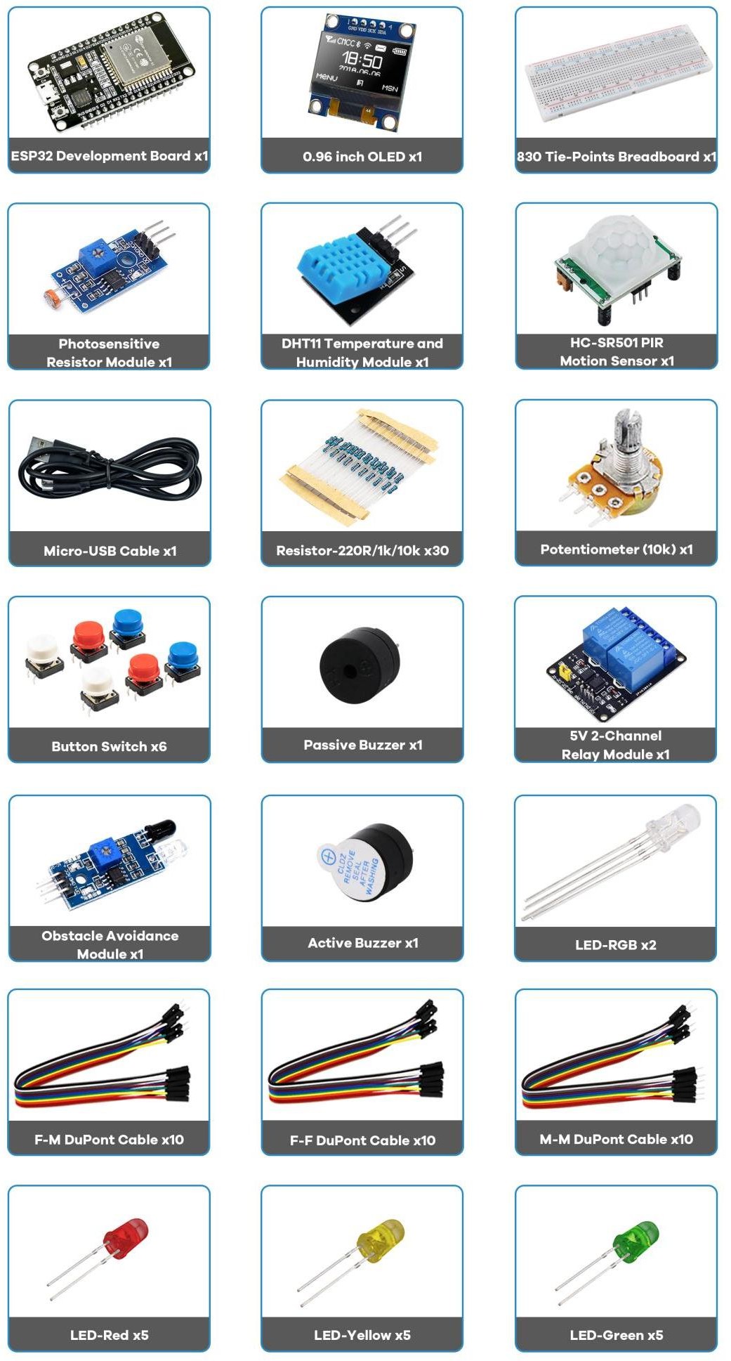
Core
| Part | What it is | How to identify | Polarity / notes | Used in |
|---|---|---|---|---|
| ESP32 DEVKIT V1 | The microcontroller: dual‑core + Wi‑Fi/BT | Black PCB, metal ESP‑WROOM‑32 can, micro‑USB, EN + BOOT | 🔴 logic is 3.3 V | All |
| Breadboard (830 pts) | Solderless build surface | White plastic, rows of holes + side rails | ⚪ rails = +/−; inner rows connect in 5s | All |
| Micro‑USB cable | Power + code upload | Standard micro‑USB | ⚪ use a data cable | All |
| Jumper wires (M‑M, M‑F, F‑F) | Connect points | Coloured wires with pins/sockets | ⚪ colour is for your clarity | All |
Outputs
| Part | What it is | How to identify | Polarity / notes | Used in |
|---|---|---|---|---|
| LED (red/yellow/green) | A diode that glows | 5 mm dome, one leg longer | 🔴 long leg = + ; needs 220 Ω | P1, P3, P5, P8, P14 |
| RGB LED (common cathode) | Three LEDs in one | 4 legs; longest = shared cathode | 🔴 cathode → GND; anodes via 220 Ω | P6 |
| Active buzzer | Beeps when powered | Sealed case, often a + mark | 🔴 + → GPIO, − → GND | P4 |
| Passive buzzer | Tones only when fed a signal | Open PCB visible underneath | 🔴 driven by PWM / tone() | P3 (going further) |
| 5 V 2‑channel relay | Switch for bigger loads | Blue box(es), screw terminals + IN pins | 🔴 VCC=5 V; COM/NO/NC on load side | P7 |
Inputs & sensors
| Part | What it is | How to identify | Polarity / notes | Used in |
|---|---|---|---|---|
| Pushbutton | Momentary switch (digital in) | Small 4‑leg tactile button | ⚪ pair with a 10 kΩ pull resistor | P1, P8 |
| Potentiometer (10 kΩ) | Variable resistor → analog in | Knob with 3 legs | ⚪ outers to 3.3 V/GND, middle = wiper | P2 |
| DHT11 module | Temperature + humidity | Blue box, 3 pins (−, +, S) | 🔴 +→3.3 V, −→GND, S→data | P9, P14 |
| HC‑SR501 PIR | Motion (infra‑red) sensor | White dome lens, two orange trimmers | 🔴 VCC=5 V, OUT = HIGH on motion | P4 |
| SSD1306 OLED (0.96″) | 128×64 I²C display | Small glass screen, 4 pins | 🔴 SDA 21, SCL 22, addr 0x3C | P10 |
| Photoresistor (LDR) module | Light sensor | PCB with a squiggly‑top sensor | 🔴 VCC/GND + analog/digital out | P2 (going further) |
| Obstacle‑avoidance module | IR proximity detector | PCB with two IR LEDs + trimmer | 🔴 VCC/GND + digital OUT | P4 (going further) |
Passive components
| Part | What it is | How to identify (5‑band) | Used in |
|---|---|---|---|
| Resistor 220 Ω | Limits current (LEDs) | Red·Red·Black·Black·Brown | LED projects |
| Resistor 1 kΩ | General purpose | Brown·Black·Black·Brown·Brown | as needed |
| Resistor 10 kΩ | Pull‑up / pull‑down | Brown·Black·Black·Red·Brown | P1, P8 |
Read 5‑band resistors with the tolerance band (Brown, ±1%) on the right. First band tells them apart: Red starts 220 Ω, Brown starts 1 kΩ and 10 kΩ. All resistors are ⚪ not polarized.
Parts with a "Going further" path
The photoresistor, passive buzzer, and obstacle‑avoidance module aren't part of the main build in Projects 1 to 10, but each has a "Going further" section showing exactly how to wire and code it, reusing a project you've already built:
- Photoresistor → Project 2's "Going further: swap in a photoresistor (LDR)": same ADC pin, same code, more light → higher reading.
- Passive buzzer → Project 3's "Going further: melodies on the passive buzzer": same PWM pin,
ledcWriteTone()instead ofledcWrite(). - Obstacle‑avoidance module → Project 4's "Going further: swap in the obstacle‑avoidance module": same digital pin, same
digitalRead()logic as the PIR.
Glossary of terms
Words this course uses constantly, in the order you're likely to meet them.
| Term | Meaning | First shows up |
|---|---|---|
| SoC (System‑on‑a‑Chip) | One chip combining a processor, memory, and peripherals like Wi‑Fi and Bluetooth | Foundation 2 |
| GPIO (General‑Purpose Input/Output) | A pin whose job (input, output, ADC, PWM, ...) you choose in code | Foundation 2, every project |
| ADC (Analog‑to‑Digital Converter) | The hardware that turns a voltage into a number | Project 2 |
| PWM (Pulse‑Width Modulation) | Rapidly switching a pin on and off to fake an analog output | Project 3 |
| Duty cycle | The fraction of each PWM cycle spent HIGH; what actually sets brightness or power | Project 3 |
| I²C | A two‑wire bus (SDA/SCL) where many addressed devices share the same two pins | Foundation 1, Project 10 |
| HTTP | The text‑based request/response protocol a browser and this kit's web‑server projects speak | Project 5 |
| Callback | A function you write but never call yourself; a library calls it when something happens | Project 11, Project 12 |
| MQTT | A lightweight publish/subscribe protocol for devices that aren't always reachable | Project 11 |
| Broker | The server in the middle of MQTT that routes published messages to subscribers | Project 11 |
| Payload | The actual data inside a message, as opposed to its address, topic, or headers | Project 11, Project 12 |
| NVS (Non‑Volatile Storage) | The ESP32's small flash partition for values that survive a reboot | Going Further |
| NTP (Network Time Protocol) | How a device with no clock of its own gets the real time from the internet | Going Further |
🎯 Knowledge Check
1. What color bands mark a 220 ohm resistor in this kit's 5-band code?
2. What is the difference between an active buzzer and a passive buzzer?
3. How do you identify the anode (positive leg) of a standard LED?
4. What does the DHT11 sensor measure?
Ask about this course
Ask about wiring, code, or troubleshooting for any project in this kit.