Project_7_ESP32_Relay_Web_Server.ino, then open it in the Arduino IDE (setup: Foundation 3). Needs the ESP Async WebServer + AsyncTCP libraries and your Wi-Fi credentials.
A relay module rated "10 A 250 V AC" describes the contacts, not a finished, certified product. Wiring it to mains for real, beyond this project's LED demo, also needs mains‑rated wire and connectors, an enclosure that keeps bare terminals out of reach, and ideally a circuit protected by a GFCI/RCD. Treat the module as one part of a mains‑safe build, not the whole thing.
diagram.json above and paste its wiring in to load the circuit.
🎯 Objective
By the end of this project, you will:
- Understand what a relay does, and why it lets a 3.3 V pin switch a mains-voltage load.
- Read a relay module's terminals: COM, NO and NC, and pick the right pair.
- Recognise active-low control, where a LOW signal turns the relay on.
- Use the ESP Async WebServer library and see why it replaces the hand-written request loop of Projects 5 and 6.
- Serve a page stored in flash with
PROGMEM, filled in at send time by a template processor. - Read query parameters such as
?relay=1&state=1instead of parsing the URL by hand.
1What a relay is
A relay is an electrically‑operated switch. A small coil current (from an ESP32 GPIO) flips a mechanical contact, connecting or disconnecting a separate higher‑power circuit: the two sides electrically isolated.
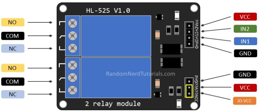
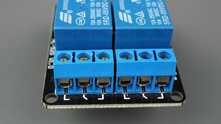
Switched side: COM / NO / NC
- COM: the wire you're switching.
- NO (Normally Open): off until triggered → use for off by default.
- NC (Normally Closed): on until triggered → use for on by default.
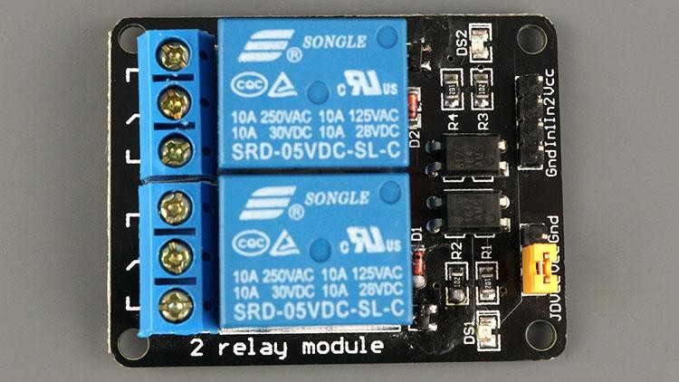
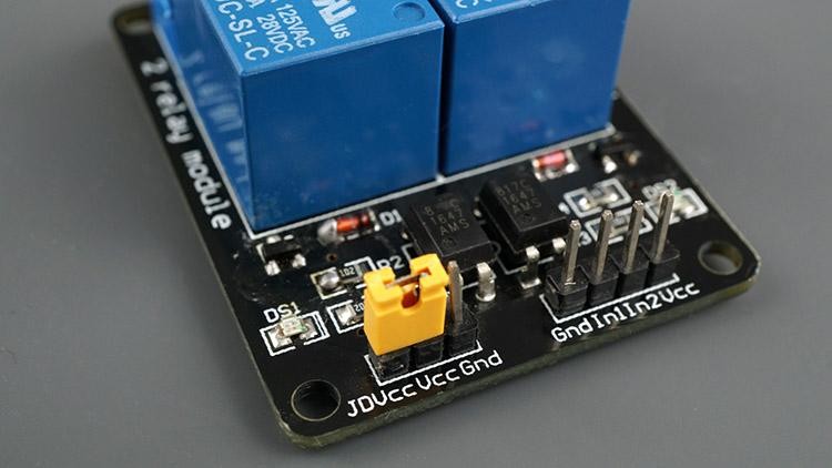
Control side: VCC / GND / IN
Inductive loads and flyback protection
Most relay modules, including this kit's, already carry a small flyback diode across the relay's own coil. That protects the control side (the ESP32) from the voltage spike a coil produces the instant it switches off.
The switched side needs its own protection only if the load itself is inductive: a motor, a solenoid, a fan, anything built around a coil. Switching an inductive load off makes it try to keep current flowing, which can arc across the relay's contacts and wear them out early, and can throw electrical noise back down the wiring. The fix is a snubber across the load: a diode wired to only conduct the reverse spike for DC loads, or an RC snubber for AC loads. This project's LED isn't inductive, so none of this applies here, but it's the first thing to add if you later switch a motor or a solenoid through this relay.
The datasheet: why the module needs more than just a relay
This board is more than a bare relay wired to two pins: it is built specifically so a 3.3 V microcontroller pin can drive it safely. Three parts on the board make that possible, and the two datasheets below document all three:
- A driver transistor, because a GPIO alone cannot supply what the coil needs. The
INpin only has to source 15-20 mA to trigger a channel, well inside a single ESP32 GPIO's drive capability, but the relay coil itself draws over 100 mA at 5 V. The transistor on the board takes that small trigger current and switches the larger coil current, the same current‑amplification job a transistor always does. - An opto‑coupler per channel (marked 817C in the schematic, an 817‑series part), sat between the
INpin and that driver transistor. It carries the ON/OFF signal as light across a physical gap, not a wire, so there is no continuous electrical path between the ESP32's ground and the relay/coil side. That is the "optically isolated" in the module's name, and it buys you two things: it protects the ESP32 from a fault or voltage spike on the switched side, and it prevents a ground loop (stray current that flows when two circuits share a ground but sit at slightly different potentials). - The flyback diode covered above, protecting the control side from the coil's own turn‑off spike.
A few more facts straight from the datasheets, worth knowing before you wire this module into a real project:
- Contact rating: the SPDT relays are rated DC 30 V/10 A or AC 250 V/10 A, the numbers printed directly on each relay's case and the source of the "10 A 250 V AC" figure in the safety note above.
- Trigger logic: confirmed active LOW by both datasheets: the relay energizes (and its onboard LED lights) when
INgoes LOW, and releases on HIGH. That is exactly the behaviour the sketch's!wantOnline accounts for. - JD‑VCC, the relay's own power pin (this board's silkscreen prints it as JD‑VCC, matching the SunFounder datasheet below; the Handson Technology datasheet's schematic labels the same pin RY‑VCC): leave the jumper on and both the opto‑coupler input and the coil share the ESP32's 5 V supply, the simplest wiring, and what this project uses. Remove it and feed JD‑VCC from its own separate 5 V supply and the coil no longer draws from the ESP32's rail at all: full electrical isolation, not just signal isolation, worth doing once you're switching something failure‑prone.
Datasheets (included in this project folder, download for the full schematics, module dimensions, and reference Arduino/Raspberry Pi sample code):
2Install the required libraries
Why we switch to a web-server library now. Projects 5 and 6 hand-rolled the HTTP parsing: reading bytes one at a time, watching for the blank line, and searching the raw request text yourself. That was worth doing once so you could see what a request and response actually look like. From here on, that plumbing does not change project to project, so this project switches to the ESP Async WebServer library: it parses the request, matches a URL to a handler you register, and answers many clients without blocking loop(), the same non-blocking idea millis() introduced in Project 4.
This project uses the asynchronous server libraries: install both:
- ESP Async WebServer
- AsyncTCP (ESP32)
Add each via Sketch → Include Library → Add .ZIP Library…, then restart the IDE.
3Wiring the Circuit
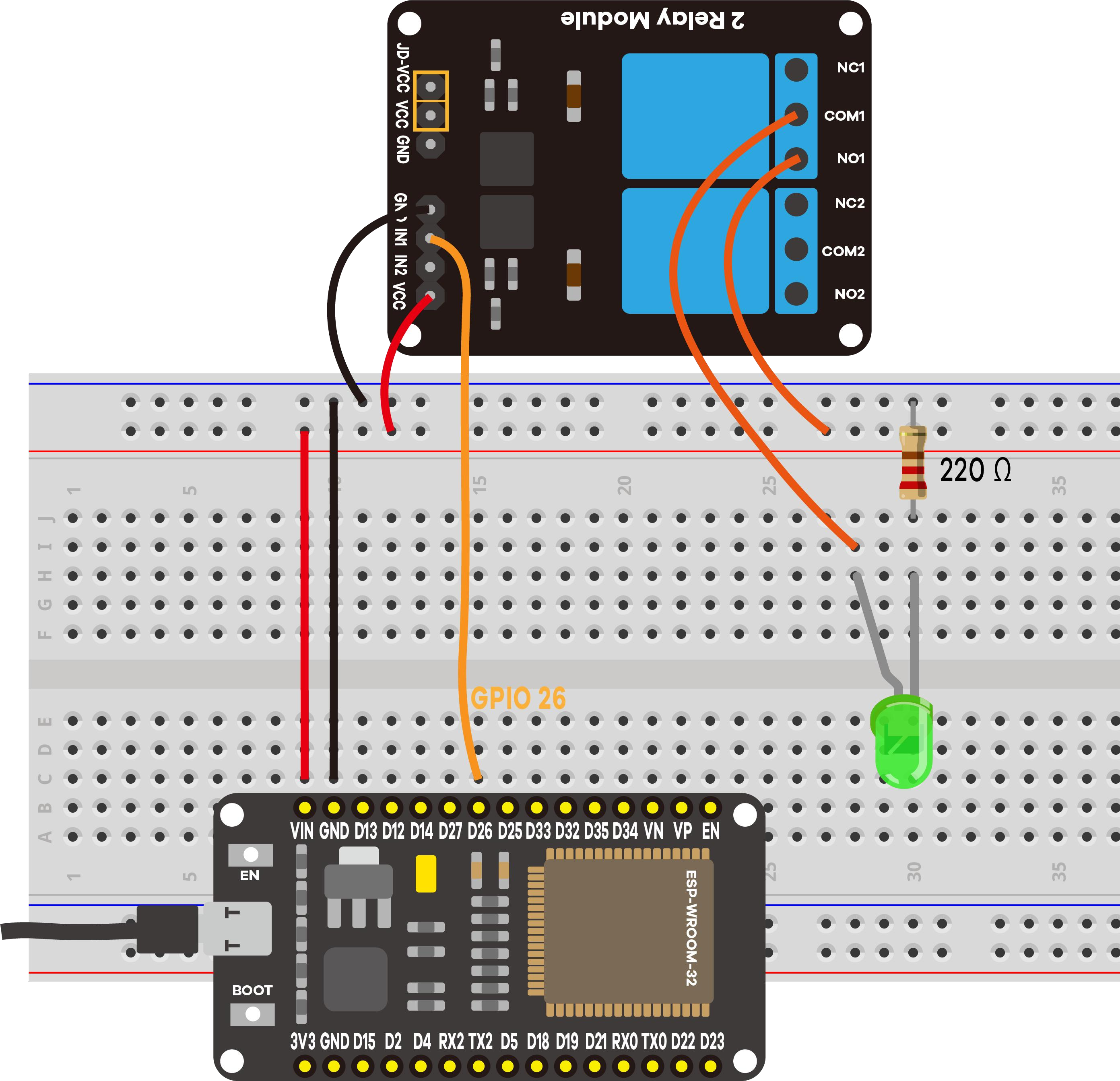
- Relay VCC → VIN (5 V) · GND → GND
- Relay IN1 → GPIO 26 (IN2 → GPIO 27 for channel 2)
- Switched side: LED (with 220 Ω) through COM → NO
Going further: wiring the second channel
The sketch already drives both relay channels, and the web page already shows two toggle switches (NUM_RELAYS = 2); the wiring above only demoes channel 1 to keep the first build simple. To see both work, wire a second LED (with its own 220 Ω resistor) through channel 2's COM → NO, exactly like channel 1's, and confirm "Relay #2" clicks and lights it from the web page too.
4Upload & use
Set your Wi‑Fi credentials, upload, open Serial Monitor at 115200, press EN/RESET:
==============================================
 Project 7: ESP32 Relay Web Server
==============================================
2 relay(s), mode: Normally Open (NO)
Relay #1 -> GPIO 26
Relay #2 -> GPIO 27
Connecting to Wi-Fi: MyNetwork
....
Wi-Fi connected!
Open this address in your browser:  http://192.168.1.42
----------------------------------------------
[WEB] Relay #1 -> ON
Open the address; flip a toggle → the relay clicks and the clean line above prints.
5Code Walkthrough: Understanding the Sketch
This sketch looks different from Projects 5 and 6, and the difference is worth understanding: the async library takes over the request handling you previously wrote by hand.
Step 1: Configuration at the top
#define RELAY_NO    true            // relays wired Normally Open
#define NUM_RELAYS  2               // how many relays on the module
int relayGPIOs[NUM_RELAYS] = {26, 27};

AsyncWebServer server(80);
Everything you might change lives in one block. relayGPIOs is an array, so adding a third relay means adding a pin and raising NUM_RELAYS: no other code changes. RELAY_NO records how the relay is wired, which decides the logic further down.
Step 2: the web page, stored in flash
const char index_html[] PROGMEM = R"rawliteral(
<!DOCTYPE HTML><html>
  ...
  %BUTTONPLACEHOLDER%
  ...
)rawliteral";
R"rawliteral( ... )rawliteral"is a raw string literal: everything between the markers is taken literally, so HTML can contain quotes and newlines without escaping. Compare Project 5, where every line was a separateclient.println().PROGMEMkeeps the page in flash instead of copying it into RAM at startup. The ESP32 has plenty of flash and much less RAM.
%BUTTONPLACEHOLDER% is a marker the library replaces when the page is sent.
Step 3: setup() puts the relays in a safe state, then registers routes
for (int i = 1; i <= NUM_RELAYS; i++) {
  pinMode(relayGPIOs[i-1], OUTPUT);
  if (RELAY_NO) digitalWrite(relayGPIOs[i-1], HIGH);   // NO: HIGH = off
}
Starting with every relay off matters more here than with LEDs: a relay that switches on at power-up would energise whatever it controls.
server.on("/", HTTP_GET, [](AsyncWebServerRequest *request){
  request->send_P(200, "text/html", index_html, processor);
});

server.on("/update", HTTP_GET, [](AsyncWebServerRequest *request){
  if (request->hasParam(PARAM_INPUT_1) && request->hasParam(PARAM_INPUT_2)) {
    int relayNum = request->getParam(PARAM_INPUT_1)->value().toInt();
    int wantOn   = request->getParam(PARAM_INPUT_2)->value().toInt();
    if (RELAY_NO) digitalWrite(relayGPIOs[relayNum-1], !wantOn);  // NO: LOW = on
  }
  request->send(200, "text/plain", "OK");
});

server.begin();
server.on(path, method, handler) says "when someone asks for this URL, run this function". The [](AsyncWebServerRequest *request){ ... } is a lambda, a function written inline. You register routes once and the library calls them for you.
!wantOn. On a normally open module the relay closes when the control pin goes LOW, so the sketch inverts the value: asking for "on" (1) writes LOW (0).Step 4: processor() builds the switches
String processor(const String& var){
  if (var == "BUTTONPLACEHOLDER") {
    String buttons = "";
    for (int i = 1; i <= NUM_RELAYS; i++) {
      buttons += /* one toggle switch per relay */;
    }
    return buttons;
  }
  return String();
}
When the library meets %BUTTONPLACEHOLDER% it calls processor("BUTTONPLACEHOLDER") and drops in whatever comes back, so the page grows automatically if you add relays. relayState() reads each pin back and returns "checked" or "", drawing each switch in the position matching the real relay.
Step 5: an empty loop()
void loop() {
}
Not a mistake. With the async server, requests are handled in the background, so nothing is left for loop() to do. That free loop() is exactly what makes room for Project 8 to poll a button while still serving pages.
Key concepts: what each line really does
| Code | What it does |
|---|---|
AsyncWebServer server(80) | An event-driven server: you register handlers and it deals with clients itself, unlike WiFiServer where you read the request byte by byte. |
PROGMEM | Keeps the page in flash rather than RAM. The ESP32 has around 520 KB of RAM but megabytes of flash. |
R"rawliteral(...)rawliteral" | A raw string: quotes and newlines need no escaping, so HTML can be pasted in as-is. |
server.on(path, HTTP_GET, handler) | Registers a route: a URL plus the function to run for it. |
request->hasParam("relay") | Checks a query parameter exists before reading it, so a malformed URL cannot crash the sketch. |
request->getParam("relay")->value() | Reads ?relay=1 and hands back "1", replacing the indexOf/substring parsing of Project 6. |
send_P(200, "text/html", index_html, processor) | Sends a page from flash (_P) and runs processor over its placeholders on the way out. |
digitalWrite(pin, !wantOn) | Inverts the command for active-low hardware: LOW energises a normally-open relay. |
void loop() {} | Deliberately empty: the async server needs no polling. |
!wantOn line above, then confirm on the real relay.6Demonstration
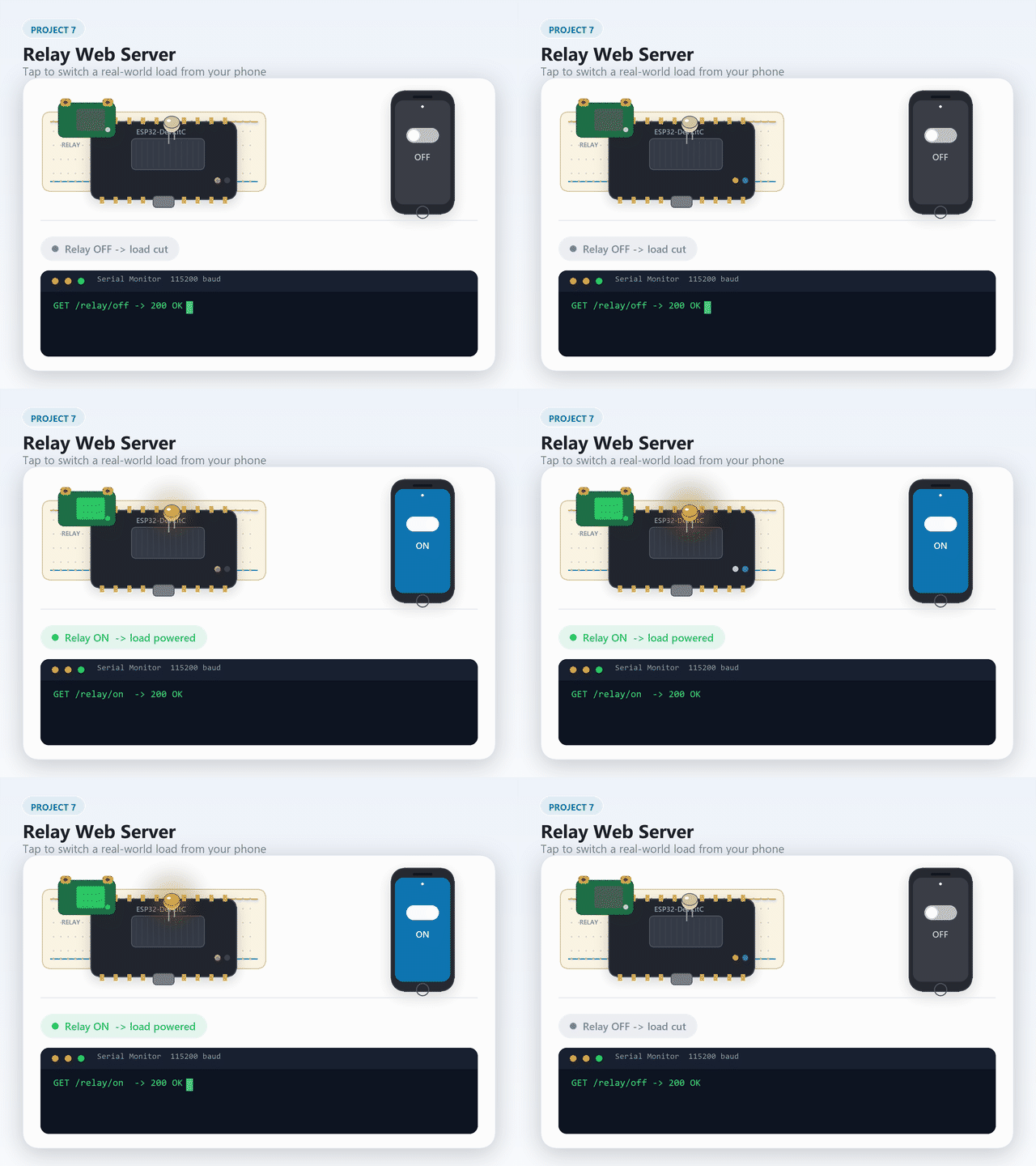
7Knowledge Check
Test your understanding.
1. On a normally-open (NO) relay module, what happens when the control pin goes HIGH?
2. What does `PROGMEM` do when storing the web page HTML?
3. Why does the sketch use `!wantOn` when writing to the relay pin?
4. What is the advantage of ESP Async WebServer over the hand-rolled HTTP parser?
5. How does the template processor `%BUTTONPLACEHOLDER%` work?
8Wrapping Up: What You've Learned
You can now switch a real electrical load from a browser, and you have met the server library the rest of the kit uses.
- A relay is an electrically operated switch: a few milliamps from a GPIO drive a coil that closes contacts rated for mains voltage, with the two sides physically isolated.
- COM/NO/NC: use COM and NO for a load that should be off by default, COM and NC for one that should be on by default.
- Many relay modules are active low. Read your module rather than assuming, and put outputs in a safe state during
setup(). - ESP Async WebServer replaces the manual request loop with routes, handling connections in the background, which is why
loop()can be empty. - Query parameters (
?relay=1&state=1) are the normal way to pass values in a URL, andhasParam()/getParam()read them safely. - Storing the page in
PROGMEMkeeps RAM free, and a template processor fills in the changing parts at send time.
Now try
- Auto-off timer: Add a relay state variable that turns the relay off automatically after 10 seconds, preventing a load from being left on indefinitely.
- Both channels: Wire a second LED through channel 2's COM/NO terminals and verify that both toggles on the web page work independently.
9Troubleshooting
| Symptom | Likely cause | Fix |
|---|---|---|
Compile error on ESP Async WebServer | Libraries missing | Install ESP Async WebServer and AsyncTCP |
| Relay clicks, load doesn't switch | Wired to NC | Use COM → NO |
| Toggle seems inverted | NO‑mode inversion (normal) | Leave the sketch as‑is |
| No click at all | IN mis‑wired / module unpowered | IN → GPIO 26/27; VCC→VIN, GND→GND |
| Relay clicks inconsistently | Opto‑coupler input current marginal (datasheet's R1) | Confirm VCC is a solid 5 V from VIN, not 3.3 V |
| Stuck on "Connecting…" | Wrong credentials / 5 GHz | Fix credentials; use 2.4 GHz |